
Why Do RF High-Power Pulse Amplifiers Need Efficient Thermal Management?
Struggling with amplifier overheating issues? This heat leads to poor performance and even failures. You need reliable thermal management to keep your systems running cool and efficiently.
Efficient thermal management is critical for RF high-power pulse amplifiers1because they generate significant heat due to power inefficiencies. This heat degrades performance, reduces component lifespan, affects reliability, and can cause system failure if not properly dissipated.
Dealing with heat is a constant challenge in high-power RF design. I remember working on a radar project in my second year after I first started my career, when insufficient cooling caused intermittent amplifier shutdowns during peak operation. It caused major delays. We learned the hard way that you can't ignore thermal management. It's not just about preventing damage; it's about ensuring the amplifier delivers the performance you expect, consistently. Let's look closer at why this is so important and how efficiency plays a big role. Understanding these details helps us build more robust and reliable systems.
How is the efficiency of an RF power amplifier determined?
Wondering how to measure amplifier efficiency? Getting it wrong means wasted power and excess heat. Understanding efficiency calculation is key to optimizing your RF system design.
RF power amplifier efficiency is primarily determined by the ratio of the RF output power delivered to the load, to the DC power consumed by the amplifier. Power Added Efficiency (PAE)2 is also commonly used.
Diving Deeper into Efficiency Metrics
Calculating efficiency seems simple, but there are nuances. The most basic measure is DC-to-RF efficiency, often just called drain efficiency (for FETs) or collector efficiency (for BJTs).
- DC-to-RF Efficiency3 (η): This is calculated as η = P_out_RF / P_in_DC.
- P_out_RF is the RF power delivered to the load.
- P_in_DC is the DC power consumed by the amplifier (Voltage x Current).
This metric tells you how much of the consumed DC power is converted into useful RF output. However, it doesn't account for the RF power needed to drive the amplifier itself. That's where Power Added Efficiency comes in.
- Power Added Efficiency (PAE)2: This is calculated as PAE = (P_out_RF - P_in_RF) / P_in_DC.
- P_in_RF is the RF power driving the input of the amplifier.
PAE is especially important for lower-gain amplifier stages or when the input drive power is significant compared to the output power. It gives a better picture of the power added by the amplifier stage itself. In my experience designing multi-stage amplifiers, looking at both η and PAE for each stage is crucial for optimizing the overall system efficiency and managing heat distribution. Lower efficiency, by either measure, directly translates to more DC power being converted into heat, which then needs to be managed.
| Factor Affecting Efficiency | Impact | Example Technologies |
|---|---|---|
| Amplifier Class | Major impact (Class A < AB < B < F, etc.) | A, AB, F, Doherty |
| Device Technology | Affects intrinsic efficiency, operating voltage | GaN, LDMOS, GaAs |
| Operating Frequency | Efficiency generally decreases with frequency | S-Band vs X-Band |
| Output Power Level | Peaks near saturation, drops at back-off | Compression Point |
| Matching Networks | Losses reduce overall efficiency | Input/Output Match |
What disadvantages do RF amplifiers have?
Think RF amplifiers are perfect solutions? They have limitations that can cause headaches. Ignoring these drawbacks leads to unexpected performance issues and design challenges.
RF amplifiers suffer from several disadvantages. Key ones include inefficiency causing heat, non-linearity creating signal distortion, limited operating bandwidth, inherent noise addition, and potential instability requiring careful design.
Understanding Amplifier Limitations
Every component has trade-offs, and RF amplifiers are no exception. Knowing these helps manage expectations and design around them.
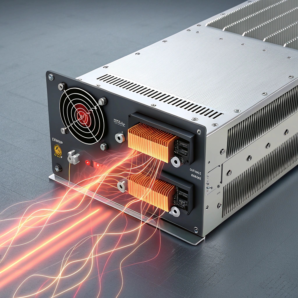
First, as we've discussed, inefficiency is a major one, especially in high-power pulse amplifiers. Power that isn't converted to RF output becomes heat. I've seen amplifiers needing bulky heatsinks or even liquid cooling just to handle the wasted power. This directly impacts size, weight, cost, and system reliability.
Second, non-linearity is a constant battle. Amplifiers don't perfectly replicate the input signal at higher power. This causes problems like:
- Harmonics: Unwanted signals at multiples of the fundamental frequency.
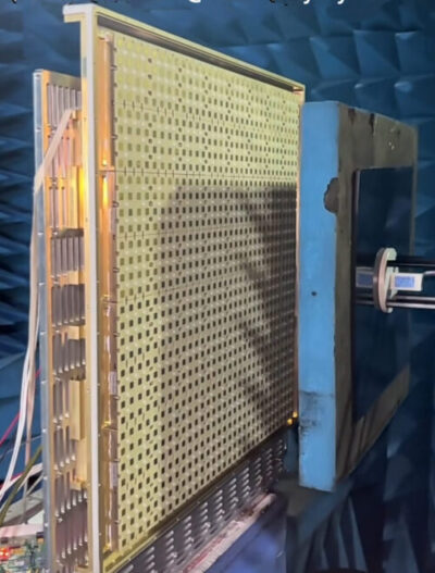
- Intermodulation Distortion (IMD): New frequencies generated when multiple signals are amplified simultaneously. This is critical in communication and radar systems like Jacky's phased arrays, where signal purity is vital.
- Gain Compression: Gain decreases as the input power increases, limiting the linear operating range.
Third, limited bandwidth is common. Amplifiers are often designed to work best over a specific frequency range. Achieving high power, high efficiency, and wide bandwidth simultaneously is very challenging.
Fourth, amplifiers add noise to the signal, quantified by the Noise Figure (NF). While less critical in high-power stages compared to low-noise amplifiers (LNAs), it still contributes to the overall system noise floor.
Finally, stability can be an issue. Amplifiers can oscillate under certain load or source conditions if not designed carefully with proper matching and bypassing. I remember spending weeks stabilizing a prototype amplifier that kept oscillating at certain frequencies. It requires careful analysis and design. These disadvantages mean we need careful design and sometimes accept compromises.
What does RF efficiency actually mean?
Heard the term "RF efficiency" thrown around? It sounds simple, but its real meaning is vital. Misunderstanding it can lead to selecting the wrong amplifier or underestimating cooling needs.
RF efficiency simply describes how effectively an amplifier converts the DC power it consumes into the RF signal power it outputs. Higher efficiency means less power is wasted as heat.
Getting to the Core of Efficiency
At its heart, RF efficiency is about energy conversion. We feed DC power (voltage and current) into the amplifier's active devices (like transistors). We also feed a smaller RF signal into the input. The goal is to get a much larger RF signal at the output.
The basic formula we discussed earlier, η = P_out_RF / P_in_DC, captures this fundamental idea. If an amplifier consumes 100 Watts of DC power and produces 50 Watts of RF power, its efficiency is 50%. The remaining 50 Watts isn't lost entirely; most of it is converted into heat within the amplifier's components.
Why does this matter so much, especially for high-power pulse amplifiers? Because the wasted power (heat) scales with the inefficiency. A 1 kW pulsed amplifier operating at 50% efficiency generates 1 kW of heat during the pulse. If it were only 30% efficient, it would generate over 2.3 kW of heat for the same 1 kW RF output! That's a huge difference in thermal load.
Factors influencing efficiency include:
- Amplifier Class: Class A is very linear but inefficient (typically < 25%). Class B, AB, C, D, E, F, and architectures like Doherty trade linearity for much higher efficiency (often > 50-70% or more).
- Device Technology: Gallium Nitride (GaN) technology, which I've worked with extensively, offers significantly higher efficiency at high frequencies and power levels compared to older LDMOS or GaAs technologies.
- Operating Point: Efficiency often peaks when the amplifier is operating close to its maximum output power (saturation). When backed off for better linearity, efficiency usually drops.
Understanding this helps us choose the right amplifier type and technology, predict thermal loads, and design appropriate cooling solutions. For pulsed systems, we also consider the efficiency during the pulse versus the average efficiency over time.
How do we measure the power efficiency of amplifiers?
Confused by different efficiency terms like PAE and DC efficiency? Using the wrong metric can mislead your design choices. Knowing which efficiency measure to use, and when, is crucial.
We primarily measure power efficiency using DC-to-RF efficiency (η), which is RF output power divided by DC input power, and Power Added Efficiency (PAE)2, which also accounts for the RF input power.
Comparing Key Efficiency Metrics
While both DC efficiency and PAE measure how well an amplifier uses power, they tell slightly different stories. Choosing the right one depends on the amplifier's gain and its role in the system.
Let's revisit the formulas:
- DC Efficiency (η_DC): η_DC = P_out_RF / P_in_DC
- Power Added Efficiency (PAE)2: PAE = (P_out_RF - P_in_RF) / P_in_DC
Imagine an amplifier stage with high gain. Let's say P_in_DC = 100 W, P_out_RF = 60 W, and P_in_RF = 0.1 W (high gain).
- η_DC = 60 W / 100 W = 60%
- PAE = (60 W - 0.1 W) / 100 W = 59.9%
In this case, η_DC and PAE are almost identical because the RF
-
Explore this link to understand the critical role of thermal management in RF high-power pulse amplifiers and how it affects performance. ↩
-
Learn about PAE and its significance in optimizing RF amplifier performance and efficiency through this informative resource. ↩ ↩ ↩ ↩
-
Understanding DC-to-RF Efficiency is crucial for designing efficient amplifiers; this resource will clarify its measurement and importance. ↩