
What Is a Phased Array Antenna?
Simply put, a phased array antenna is an advanced antenna system that steers its beam electronically without physically rotating the antenna. Its core building block is many individual antenna elements (radiating elements) arranged in a defined array. Behind each element sits a phase/amplitude controller, typically a phase shifter.
A phased array electronically controls each element’s phase and amplitude to create constructive and destructive interference, steering narrow beams at microsecond speeds without mechanical motion, enabling multi-beam, multi-mission operation with high reliability and strong anti-jamming performance.
1. Core Working Principle: Wave Interference
The operation of a phased array relies on beamforming and coherent interference in physics.
- Constructive interference: When the peaks of two or more waves align, they add, and the signal strengthens.
- Destructive interference: When a peak meets a trough, they cancel, and the signal weakens.
A phased array manipulates this interference by precisely controlling the phase of the transmit/receive signal at each element (that is, a relative time delay of the waveform).
Assume we have a row of elements and we want the beam to point to the right.
1) Simultaneous transmission: If all elements transmit at the same time, the wavefront is planar, and the beam points normal to the array, straight ahead.
2) Sequential delayed transmission: If the leftmost element transmits first, and each element to the right transmits with a small incremental delay, the superposed wavefront tilts, and the beam points to the right.
3) Electronic phase control: In real phased arrays, this “delay” is controlled by phase shifters. By applying a specific phase offset to each element’s signal, we achieve the same effect electronically, steering the beam in space.
By using a computer to control each element’s phase in real time and with precision, the beam can scan, hop, and change shape within extremely short times.
2. Key Technical Features and Advantages
Compared with traditional mechanically scanned antennas, phased arrays offer revolutionary advantages:
1) Inertialess electronic scanning
- Very fast: Beam steering occurs at the speed of electromagnetic control, often within microseconds or nanoseconds. The system can track multiple targets or switch between directions rapidly.
- High flexibility: It can generate multiple independent beams to perform search, tracking, communications, and other tasks at the same time.
2) High reliability and redundancy
Among hundreds or thousands of elements, a small number of failures only causes slight performance loss rather than total failure, achieving “graceful degradation.”
3) Multi-functionality
The same antenna can support radar, electronic warfare, and communications at once. It is the core of “integrated RF systems” on modern military platforms such as warships and fighter aircraft.
4) Low probability of intercept and strong anti-jamming
The beam can be very narrow, with concentrated energy, making it hard for an adversary to intercept.
Nulls (regions of very low signal) can be steered rapidly toward jammers to suppress interference.
5) Long lifetime
It removes heavy, failure-prone mechanical scanning structures, which greatly improves reliability.
Of course, there are drawbacks:
- High cost: Large numbers of elements, phase shifters, T/R modules, and complex signal processing drive manufacturing cost.
- System complexity: Design and calibration are difficult.
- Power and thermal load: Especially for active arrays, many T/R modules generate significant heat.
3. Main Types
Phased array antennas fall into two broad categories:
3.1 Passive Phased Array
There is a single central transmitter and receiver. Phase shifters are placed between the elements and the central transceiver to control beam direction. The structure is relatively simple and lower cost, but it offers less functionality and reliability than an active array.
3.2 Active Phased Array
This is the current mainstream and high-end approach. Each element (or subarray) directly connects to a full T/R module that integrates a miniaturized transmitter, receiver, phase shifter, and amplifiers.
Advantages:
- Higher reliability (distributed sources; single-point failures have limited impact).
- Higher efficiency (lower loss through amplification stages).
- Greater flexibility (for example, adaptive beamforming).
- Performance far exceeds passive arrays.
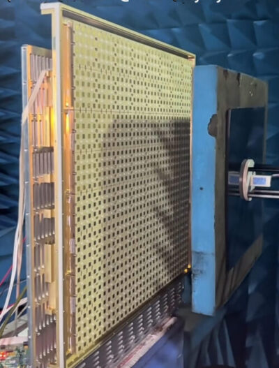
4. Antenna Element Components
Antenna elements couple electromagnetic energy between the T/R module and free space. They usually sit on a lattice or conform to a surface and radiate efficiently. Satellite ground stations require dual polarization and must support both LHCP and RHCP simultaneously.
However, achieving high cross-polarization isolation in dual-polarized elements is not easy. Classic dual-polarized antennas, such as crossed dipoles and crossed slots, replicate a radiator and place it orthogonally to the original. In recent years, patch antennas excited in two orthogonal modes, each corresponding to one polarization, have become very popular.
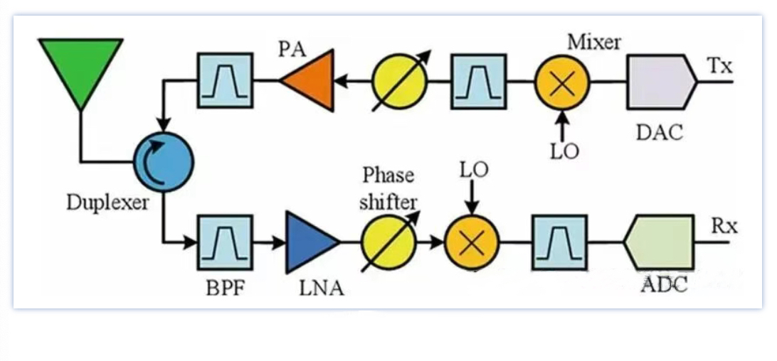
Typical layout of a modern T/R module
5. T/R Modules
T/R modules are often seen as the most important part, accounting for about half of the phased array’s total cost. Over recent decades, T/R modules have advanced significantly in materials, design, and layout. Figure 1 shows a typical modern T/R module layout. It includes core blocks such as the duplexer, filters, phase shifters, power amplifier (PA), low-noise amplifier (LNA), mixer, local oscillator (LO), analog-to-digital converter (ADC), and digital-to-analog converter (DAC).
5.1 Duplexer
A satellite ground station needs full-duplex communications to handle uplink and downlink at the same time. This uses a component called a duplexer (or circulator). It isolates the receive path from the transmit path while suppressing interference and allows both to share a common antenna element.
5.2 Filters
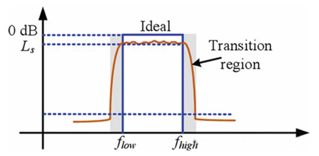
A filter is a frequency-selective component that passes signals within a target band while rejecting out-of-band signals. For example, on the receive path, the filter following the duplexer is a band-pass filter (BPF). It passes the received signal and attenuates leakage and coupling from the transmit path. This is crucial in satellite communications, which use frequency-division multiplexing, while radar uses time-division multiplexing. Figure 2 shows a typical BPF transfer function. Ideally, we want full pass within a defined range and full rejection outside. The filter’s insertion loss indicates in-band attenuation. There is a gradual transition between the passband and stopband. Filter design aims for a steep transition with acceptable insertion loss.
5.3 Power Amplifier (PA)
A PA amplifies the input signal before the antenna element radiates it into free space. Due to amplifier nonlinearity, it generates output distortions, including higher-order harmonics and intermodulation products.
5.4 Low-Noise Amplifier (LNA)
The LNA amplifies the signal received from the element and sends it to subsequent components such as mixers and filters. Every component in the receive chain adds noise. The output SNR (SNRout) of a given device is lower than the input SNR (SNRin). The noise factor F describes the SNR degradation introduced by the device.
F = (SNRin) / (SNRout)
For cascaded components, the overall noise factor is:
F = F1 + (F2 − 1)/G1 + (F3 − 1)/(G1 G2) + …
Here, Fi is the noise factor, and Gi is the gain of the i-th component.
This shows the first RF component sets the final system noise factor. Thus, any passive part before the first amplifier (such as cables and filters) hurts the noise figure. Likewise, components after a high-gain amplifier have little effect on total noise. A high-performance LNA has low noise factor and high gain, so the total noise factor is dominated by the first LNA. To achieve good link sensitivity, the LNA must be placed as close to the antenna element as possible.
5.5 Phase Shifter
A phase shifter changes the phase of a signal. An ideal phase shifter has low and nearly equal insertion loss across all phase states. The phase shift is constant versus frequency, so phase shifters suit narrowband beamforming. For wideband beamforming, true time delay (TTD) units are needed, where delay is a linear function of frequency.
5.6 Mixing and Local Oscillator
The LO uses a PLL with a crystal oscillator to generate the required frequency. In the Rx chain, a mixer downconverts the input from RF to IF. In the Tx chain, a mixer upconverts the output from IF to RF. A mixer’s output contains sum and difference frequencies of its two inputs. A second BPF after the mixer selects the desired difference component and suppresses intermodulation products. This heterodyne frequency conversion is mature and widely used. However, maintaining wide bandwidth often requires many filters. Today, frequency conversion is not always necessary. Direct sampling can digitize RF signals directly and support larger input bandwidth.
5.7 AD/DA
An ADC converts analog signals to digital samples. A DAC performs the inverse. The ADC dynamic range is set by the effective number of bits N:
SNR(dB) = 6.02 × N + 1.76
This is the maximum dynamic range when the signal level is at full scale. We use effective bits N because it accounts for ADC non-idealities that limit achievable bits. The sampling clock synchronization of ADCs and DACs must be carefully designed to minimize timing skew. For analog beamforming and subarray-level digital beamforming, signals from multiple elements are combined before digitization to save ADCs and DACs. In element-level digital beamforming, each element has its own ADC and DAC. This higher level of digitization increases functionality and delivers better performance than earlier architectures.
6. FPGA Applications in Phased Arrays
In a phased array, the FPGA usually sits at the front end of digital beamforming and processing and performs the following core tasks.
6.1 Digital Beamforming — The Core Function
This is the primary task of the FPGA in both receive and transmit modes.
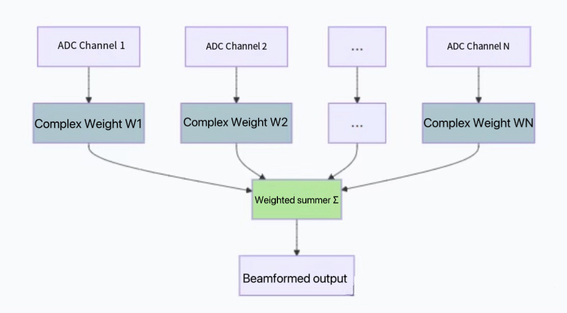
Receive beamforming:
- Each element’s analog signal is downconverted and digitized by an ADC.
- These digital streams enter the FPGA in parallel.
- The FPGA applies a complex weight to each channel computed by the beam-control computer. The weight includes the phase shift needed for pointing and amplitude taper for sidelobe reduction.
- The FPGA aligns and sums all weighted channels to form one or more beams pointing in specific directions.
Transmit beamforming:
- A baseband signal enters the FPGA.
- The FPGA replicates the signal and applies a specific pre-phase and amplitude weight for each transmit channel.
- The weighted digital streams go to their DACs, are converted to analog, upconverted, and amplified, and then radiated by the antenna. These signals interfere in space to form a transmit beam in the desired direction.
6.2 Calibration and Compensation
Phased array performance depends strongly on channel consistency. Due to manufacturing tolerances and temperature drift, channels exhibit amplitude and phase errors. The FPGA implements:
- Real-time channel calibration: Inject a known test signal. The FPGA measures each channel’s response error and computes compensation coefficients. During normal operation, it applies these coefficients in real time to keep all channels aligned.
6.3 Signal Processing and Filtering
Before or after beamforming, the FPGA also executes substantial signal processing:
- Digital down/up conversion: Move signals to baseband or IF.
- Filtering: Implement FIR, IIR, and other filters to suppress out-of-band noise and interference.
- Pulse compression: In radar, use matched filtering to improve range resolution and SNR.
- Multi-beam formation: Use parallelism to compute and generate multiple independent beams for search, tracking, and communications.
6.4 Beam Control and Scheduling
The FPGA cooperates with the host control computer:
- Interfaces: Receive commands such as beam pointing angles and operating modes.
- Lookup and computation: Store or compute “phase codes” that map angles to per-channel phase weights.
- Agile scheduling: Execute complex beam schedules with very tight timing, for example, hopping the beam from one target to another within a few microseconds.
7 Several Development Trends in Phased Arrays Antenna.
As phased array engineers with over 10 years on the front line, I have observed several development trends in phased arrays.
1) Frequency development is trending toward higher bands, reaching the terahertz range; antenna technology is evolving toward photonic/optical-wave antennas.
2) Performance is moving toward greater integration and multifunctionality; architectures are advancing toward digitization and intelligentization.
3) Technical architectures are shifting from “mast-type” to “tile-type,” and from “independent” to “distributed systems”; systems are evolving toward intelligent architectures.
4) Key MMIC chips are developing toward multifunction, multi-channel integration, high efficiency, and high power density; device technologies are trending toward GaN, SiC, and modularization.
5) Efficient thermal design is the key technology to address the challenges of high-density integration in millimeter-wave phased arrays, ensuring long-duration, reliable, and efficient operation.