
Why is it essential to test Gain Flatness, Harmonics, and Spurious Signals for a power amplifier?
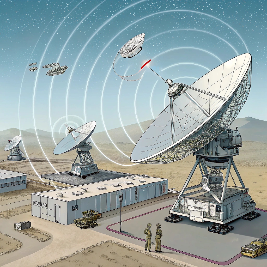
Encountering unexpected performance issues with radar systems can lead to catastrophic failures. Ensuring these tests are complete is crucial for reliability and precision.
Gain flatness measures uniformity in amplification across frequencies, harmonics assess distortion from nonlinearities, and spurious signals identify unwanted interference. These parameters ensure optimal performance and compliance within RF systems.
Testing these aspects of power amplifiers can prevent costly issues and ensure high-quality signal transmission. Let’s dive into the specifics of each test.
What’s the significance of testing Gain Flatness, Harmonics, and Spurious Signals?
Issues in these areas can cause signal degradation, affecting radar accuracy and communication systems. Testing assures system stability and signal integrity across functions.
Gain flatness maintains consistency in signal strength, harmonics minimize distortion, and controlling spurious signals prevents interference with other devices. These tests ensure compliance with industry standards and offer peace of mind in performance.

Each test serves a unique purpose in maintaining the quality and function of the power amplifier. Gain flatness ensures that an amplifier consistently boosts signals across varying frequencies without distortion or loss. A uniform gain translates to reliable signal transmission vital for radar and communication functions. Harmonics stem from nonlinear behavior in amplifiers, introducing unwanted frequencies that may disrupt intended operations. By testing for harmonics, engineers can ensure that the primary signal remains clean and focused, which is essential for accurate data handling. Spurious signals emanate from various sources such as mixer products or power supply artifacts. These can compromise the integrity of a system, leading to potential operational failures. Testing for spurious signals serves to identify and rectify interference issues, thus securing reliability in critical systems.
Test Prepration—Example: Testing C-Band 2.5KW Pulsed Power Amplifier
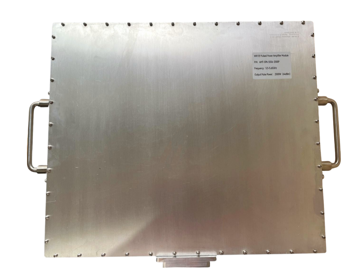
Let’s explore the testing of gain flatness, harmonics, and spurious emissions using a C-band 2.5KW pulsed power amplifier as an example.
How to Test Gain Flatness of RF High Power Pulsed Amplifiers?
Misalignments in RF systems due to gain inconsistencies can wreak havoc in precision applications.
Testing for gain flatness involves measuring an amplifier’s response across its operational bandwidth. Precise calibration and signal sweeping verify uniform gain delivery.
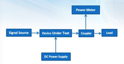
. Power Gain Testing Method:
- Calibrate the input cables of the signal source and coupler.
- Set up the test link according to Figure 1.
- Use the signal source to drive the output power of the Device Under Test (DUT) to the target level (typically saturation power or P-1).
- Keep the signal source output power constant and change the signal frequency. Use the power meter software to read the DUT output power at different frequency points.
- Data processing: DUT gain test results = DUT output power (with coupler calibration data added by default) – signal source input power + input cable loss.
Testing gain flatness requires methodical procedures and calibrated equipment. Begin by utilizing a signal generator to produce a continuous wave signal, swept through the required frequency range. Connect the amplifier and measure its output using a power meter or spectrum analyzer across distinct frequency points. The deviation in gain over the frequencies must fall within specified limits, commonly ±1 dB or less, depending on the application’s demands. Document these measurements to identify variations and implement necessary adjustments. By ensuring gain flatness, an amplifier can reliably deliver consistent power across its intended spectrum, thereby supporting seamless signal transmission crucial for precision radar or communication systems.
How to Test Harmonics of RF High Power Pulsed Amplifiers?
Random harmonics can degrade signal quality and result in inefficiencies.
Harmonic testing involves analyzing the output signal for unnecessary frequency components. Spectrum analyzers help identify and eliminate these disruptive frequencies.
. Harmonic Testing Method
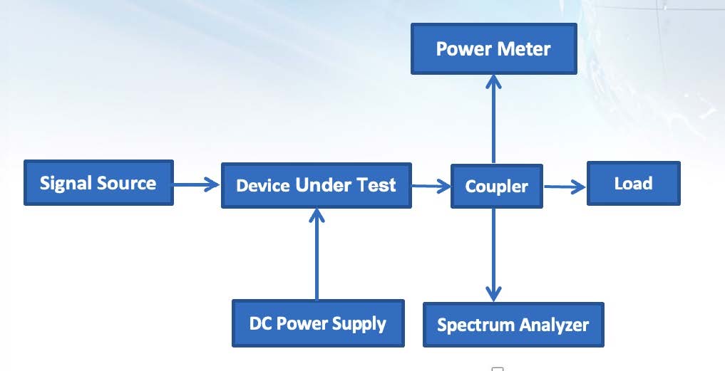
- Set up the test link as shown in Figure 4.
- Use the signal source to drive the output power of the device under test to a specified level (typically saturation power or P-1).
- Spectrum analyzer operation steps:
Frequency → Start Frequency → Enter the start frequency (usually slightly less than the test frequency) → Stop Frequency (Enter the stop frequency (usually slightly greater than the highest harmonic frequency to be tested). - If the harmonic power is low, adjust the RBW (resolution bandwidth) to lower the noise floor and locate the harmonic signal under test.
- Once the harmonic signal to be tested is found on the spectrum analyzer, the operation steps are: Peak Search → Marker → Delta → Peak Search → Next Peak, you can read the harmonic test results on the spectrum.
The process of testing harmonics in RF amplifiers is crucial to maintaining signal purity. Use a highly sensitive spectrum analyzer to capture the output spectrum of the amplifier once the primary signal is applied. The presence of higher-order harmonics, primarily the second and third, must be scrutinized as they reflect the amplifier’s nonlinear characteristics. These harmonics can be reduced using filters or bias adjustments to maintain signal integrity. Measuring harmonics is essential for ensuring low distortion levels and high precision, particularly in complex systems like phased array radar where clean signal output is mission-critical.
How to Test Spurious Signals of RF High Power Pulsed Amplifiers?
Unidentified spurious emissions can interfere with nearby devices, risking operational reliability.
Testing for spurious signals involves sweeping through frequency ranges to identify any non-fundamental emissions that don’t belong. Precise instrumentation is used to detect and mitigate intrusions.
. Spurious Signal Test Steps:
Build the test setup as shown in Figure 8.
Use a signal source to drive the output power of the Device Under Test (DUT) to the specified level (typically saturation power or P-1).
Spectrum Analyzer operation steps: Preset—Peak Search—Marker →CF (applicable for 8564, 8565 Spectrum Analyzers), set the frequency of the peak signal as the center frequency. Alternatively, press: Frequency—Center Freq—Enter Test Frequency to set the test frequency as the center frequency.
Adjust Span and RBW to find the largest spurious signal. Generally, adjust the span from GHz to MHz, switching from large to small.
Note: Adjusting Span changes the width of frequency displayed on the spectrum analyzer screen. Adjusting RBW can reduce the noise floor. Both Span and RBW must be adjusted simultaneously; otherwise, with a large Span and small RBW, the scan time will become very long.After locating the largest spurious signal, follow these Spectrum Analyzer operation steps: Peak Search—Marker—Delta—Peak Search—Next Peak. You can then read the spurious test result on the spectrum.
Effective spurious signal testing involves comprehensive spectral analysis. Initiate testing by using a signal analyzer to sweep through frequencies outside the main band of operation. Identify emissions resulting from modulation products or power supply ripple that aren’t part of the desired output. These signals can interfere with other devices or systems operating in close proximity. Document the levels and frequency positions of spurious signals to develop strategies, such as filtering or reconfiguration, to minimize their impact. Ensuring the absence of spurious emissions is vital for maintaining compliance with regulatory standards and ensuring effective and reliable system functionality.
Conclusion
Gain flatness, harmonics, and spurious signal testing are essential to the reliable operation of RF amplifiers, influencing system integrity and regulatory compliance.