
How do we verify the P1dB, IP3, Gain, and Pout of a power amplifier?
When working with high-power RF amplifiers—especially in satellite communications, radar, and electronic warfare—accurate performance verification is essential. Among all RF metrics, P1dB, IP3, Gain, and Output Power (Pout) are the most fundamental indicators used to evaluate linearity, efficiency, and system robustness.
This guide provides a clear, engineering-focused method to measure each parameter.
All steps apply to both CW and pulsed high-power amplifiers (GaN, GaAs, LDMOS).
We often see engineers struggle when they need to check these four key parameters, and this problem slows down their whole project.
To verify P1dB, IP3, Gain, and Pout, we run structured RF tests using a signal generator, spectrum analyzer, power meter, and couplers, and we check each parameter with controlled input sweeps and calibrated measurements across the working band.

We know many RF engineers who want to check these four parameters quickly, but they do not always know where to start, so they search for a simple and clear guide that gives them confidence to run the tests.
Why does Gain matter when we test a power amplifier?
We see many engineers worry about unstable gain results because unstable gain often leads to poor link budgets or unexpected failures in field tests.
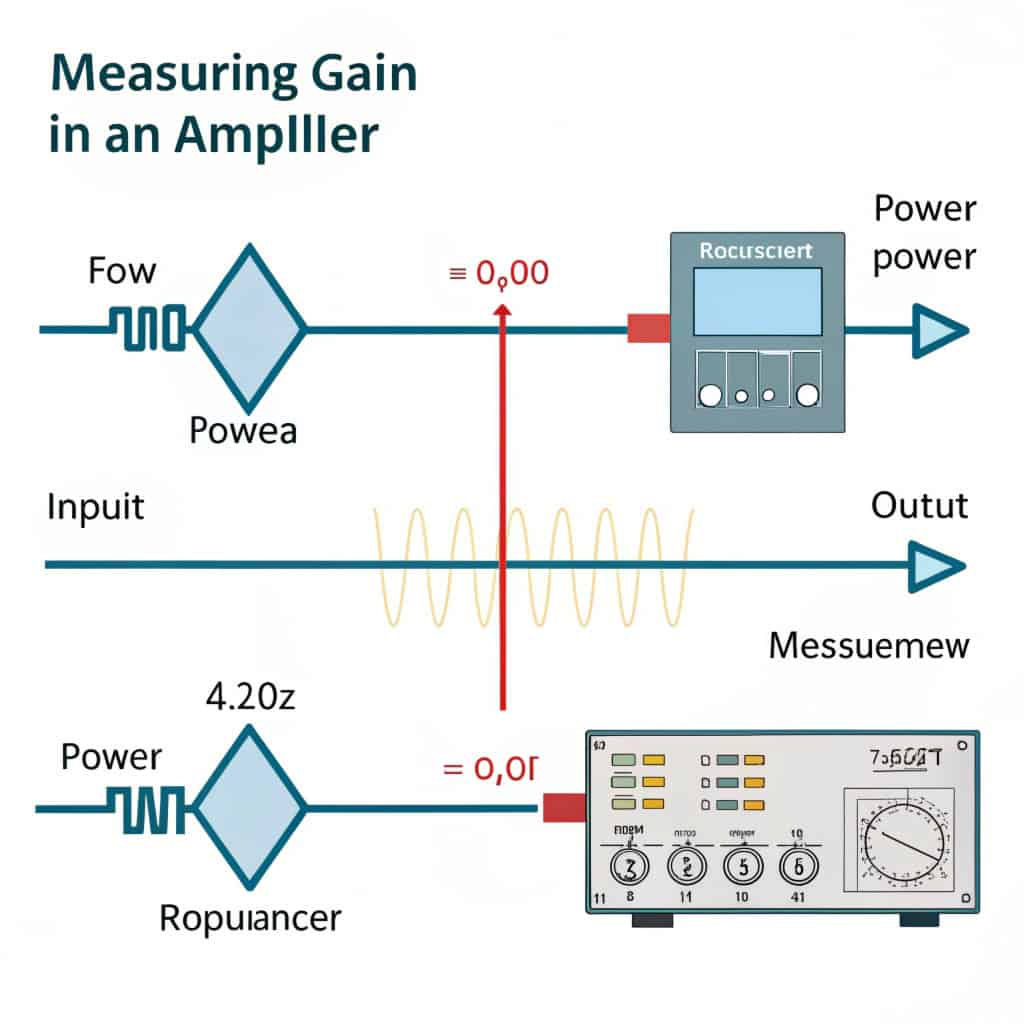
We measure gain by sending a known input power into the amplifier, reading the output power, and calculating the difference across the entire frequency band.
A deeper look at Gain testing
We rely on a simple formula to find gain: Gain = Pout − Pin. The task looks easy, but many details decide the final accuracy. We check the calibration of our signal generator and our power meter before each test. We use attenuators that have power ratings higher than the amplifier output. We always warm up the amplifier first because GaN devices drift during the first few minutes.
We run our gain test at the lower band edge, center frequency, and upper band edge. We also increase Pin slowly to see when the gain starts to compress. We check the mismatch between our cables, and we sometimes add a directional coupler to read the forward and reflected power at the same time.
Here is how we usually structure the measurement:
Steps for Gain Measurement
| Step | Action | Reason |
|---|---|---|
| 1 | Set input power | Avoid overdrive |
| 2 | Measure actual Pin | Offset cable losses |
| 3 | Measure Pout | Confirm stable power |
| 4 | Calculate gain | Main parameter |
| 5 | Sweep frequencies | Find ripple |
| 6 | Sweep input power | Check compression |
We learned early in our career that even small mistakes in Pin measurement can create big errors in system-level radar calculations. This is why we always double check the setup before we record any results.
How do we measure Pout correctly?
Many engineers rush when they measure output power, but this step decides if the amplifier meets the real system requirements.
We measure Pout with a calibrated power meter or a coupler sample port, and we increase Pin slowly until the amplifier reaches the expected rated output power.

A deeper look at Pout testing
We always protect our test equipment first. High-power amplifiers can burn connectors or damage analyzers. We place attenuators at the output and we confirm their power rating matches the amplifier. We connect our power meter through a coupler with known coupling loss so we can check power safely.
We raise the input power step by step. We watch how fast the output rises. When we see the output stop increasing linearly, we know we are close to the compression region. We also check the harmonics on a spectrum analyzer because some amplifiers create strong second or third harmonics at high power, and this can affect radar or satellite systems.
Pout Measurement Setup
| Component | Function |
|---|---|
| Signal generator | Provides input |
| Driver/attenuator | Controls Pin |
| Amplifier under test | DUT |
| High-power attenuator | Protects equipment |
| Directional coupler | Samples power |
| Power meter | Reads Pout |
We learned that in phased array radar work, Pout consistency across temperature is as important as absolute power, because it affects beam steering accuracy.
How do we verify P1dB?
Engineers often feel unsure about P1dB because they do not always have a clean method to find the exact 1 dB drop.
We find P1dB by increasing input power until the measured gain becomes 1 dB lower than the small-signal gain.

A deeper look at P1dB testing
We start by measuring the small-signal gain at a low input level. Then we increase the input step by step. We record Pout at each step. We calculate the gain each time and we watch for the first point where the gain is 1 dB less than the small-signal value.
We check P1dB at different frequencies because broadband amplifiers do not compress equally across the band. Some bands compress early, especially near the edges. We also consider thermal effects. Many GaN amplifiers show a softer roll-off when hot, so we often let the device warm up for a few minutes before taking final readings.
P1dB Analysis
| Parameter | Behavior |
|---|---|
| Gain | Drops near compression |
| Pout | Slows increase |
| Linearity | Degrades |
| Distortion | Increases |
| Thermal drift | Moves P1dB point |
We still remember a radar transmitter test early in our career where the P1dB shifted almost 1.2 dB after 10 minutes of operation. That moment taught us the importance of thermal stabilization.
How do we measure IMD3?
IMD3 (third-order intermodulation distortion) indicates the nonlinear distortion generated when two tones pass through a power amplifier. Measuring IMD3 accurately requires careful setup, especially for high-power amplifiers.
We measure IMD3 by sending two tones at low input power into the amplifier and sampling the output via a directional coupler and high-power attenuators to a spectrum analyzer. The third-order intermodulation products (2f1−f2, 2f2−f1) are recorded in dBc relative to the fundamental tones.

A deeper look at IMD3 testing
- Use two phase-stable signal generators for the tones f1 and f2.
- Combine the tones with a high-linearity combiner.
- Keep input power well below P1dB to stay in the linear region.
- Sample the high-power amplifier output with a directional coupler and appropriate attenuators to protect the spectrum analyzer.
- Measure the fundamental tones and IMD3 products at multiple frequencies.
- Subtract the test setup contribution to isolate the amplifier’s distortion.
IMD3 Measurement Breakdown
| Item | Purpose |
|---|---|
| Two signal generators | Produce two clean tones |
| Combiner | Merge tones linearly |
| Attenuator | Control Pin safely |
| Amplifier | DUT |
| Directional coupler + attenuator | Sample high-power output safely |
| Spectrum analyzer | Measure IMD3 in dBc |
IMD3 is critical in satellite and radar systems because high IMD3 generates adjacent channel interference, which can degrade total system performance.
How do we safely test high-power amplifiers?
We have seen many engineers damage their equipment during testing. Safety should always come first in high-power RF testing.
To avoid equipment damage, always verify attenuator power rating, use circulators or limiters for high VSWR, prefer directional couplers for >200 W amplifiers, and allow the amplifier to reach thermal steady state before final readings.
A deeper look at safety
High-power amplifiers can easily burn connectors, cables, or test instruments if precautions are ignored. We always double-check the rating of attenuators and make sure directional couplers are used for direct measurement. For very high power devices, we never connect the analyzer directly. We also let the amplifier run for several minutes to stabilize the temperature. This practice reduces drift in gain, P1dB, and Pout. Safety is not just about protecting instruments; it ensures reliable and repeatable measurements. We have personally learned that following these rules saves both time and money during high-power testing campaigns.
Safety Checklist
| Precaution | Reason |
|---|---|
| Verify attenuator rating | Prevent burnout |
| Use circulators/limiters | Protect against high VSWR |
| Prefer directional couplers | Avoid direct high-power measurement |
| Thermal stabilization | Ensure repeatable readings |
Summary Table of Key Measurements
| Parameter | What It Means | Test Method |
|---|---|---|
| Gain | Amplification level | Pin/Pout comparison |
| Pout | Absolute output power | Power meter / coupler |
| P1dB | Nonlinear threshold | Gain compression sweep |
| IP3 | Linearity indicator | Two-tone IMD test |
Conclusion
These four measurements, combined with proper safety practices and a clear summary table, ensure accurate and reliable high-power amplifier testing.
If you are interested in Acura’s power amplifiers for radar, satellite, or EMC applications, please visit our website: https://acuramw.com or contact us at [email protected].