What Are the 11 Key Performance Specifications for RF Power Amplifiers in Radar Systems?
As a critical component in radar systems, RF pulsed power amplifiers (PAs) play an essential role in amplifying RF signals for high-performance target detection and tracking. The performance of these amplifiers directly impacts a radar system's sensitivity, range, resolution, and overall operational efficiency, especially in demanding military and aerospace applications. With over 30 years of experience in the RF power amplifier industry, ACURAMW understands the essential technical requirements of radar system engineers, ensuring our amplifiers meet stringent performance specifications.
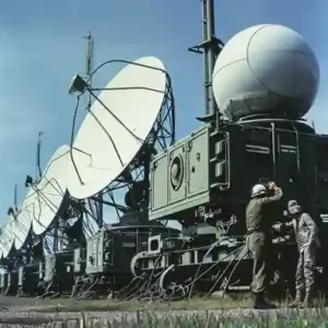
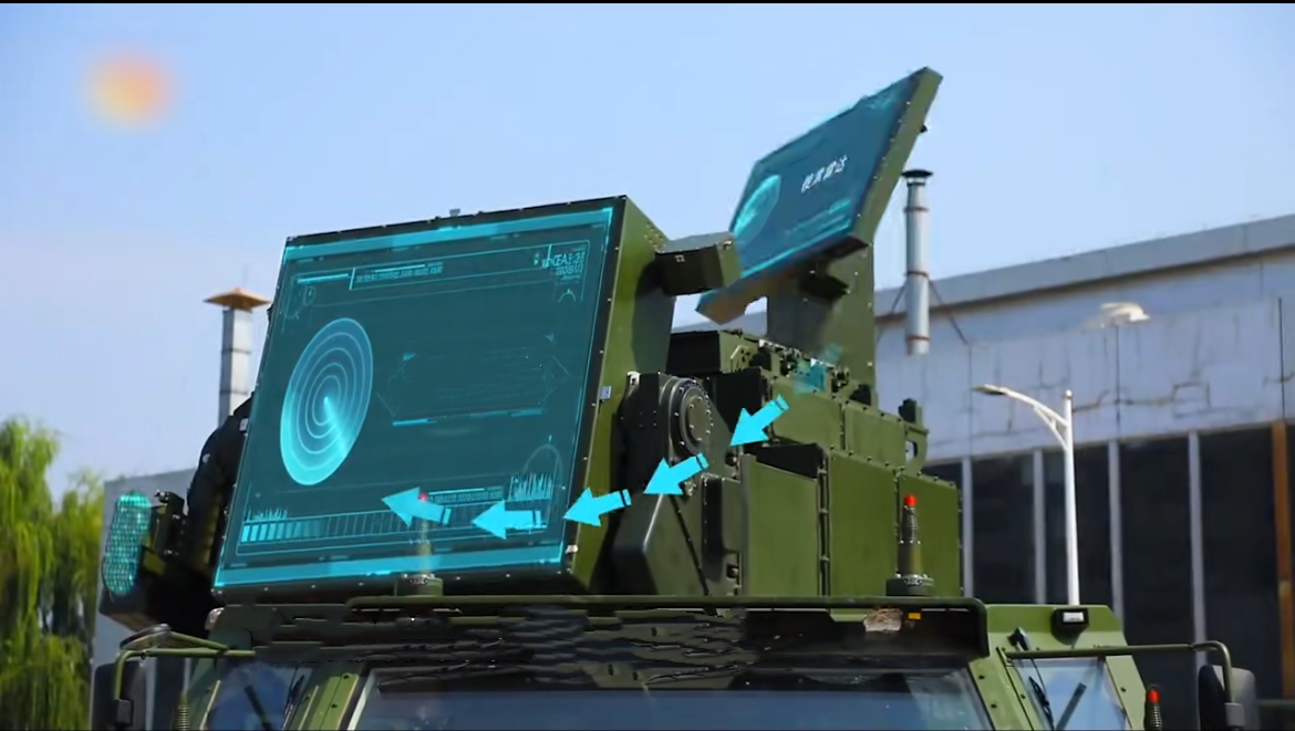
The installation and commissioning site of a military radar system
Below are 11 key technical specifications that determine the reliability, power efficiency, and operational capabilities of RF pulsed power amplifiers for radar systems.
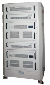
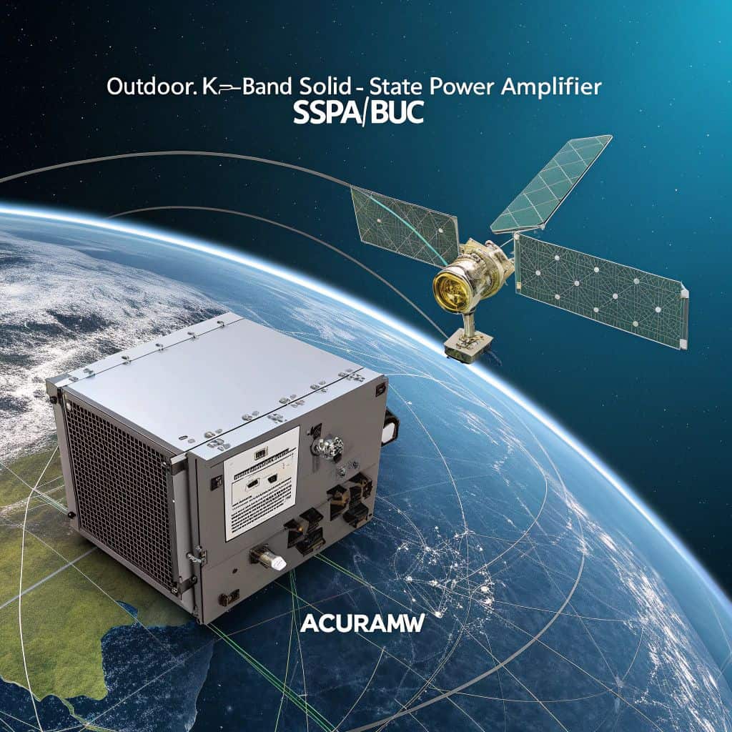
ACURAMW's C band 2000W Power Amplifier
1. Peak Output Power (P_peak)
Definition:
Peak output power refers to the maximum instantaneous power an amplifier delivers during a pulse, typically measured in watts (W).
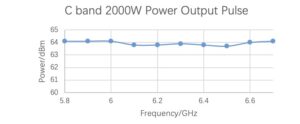
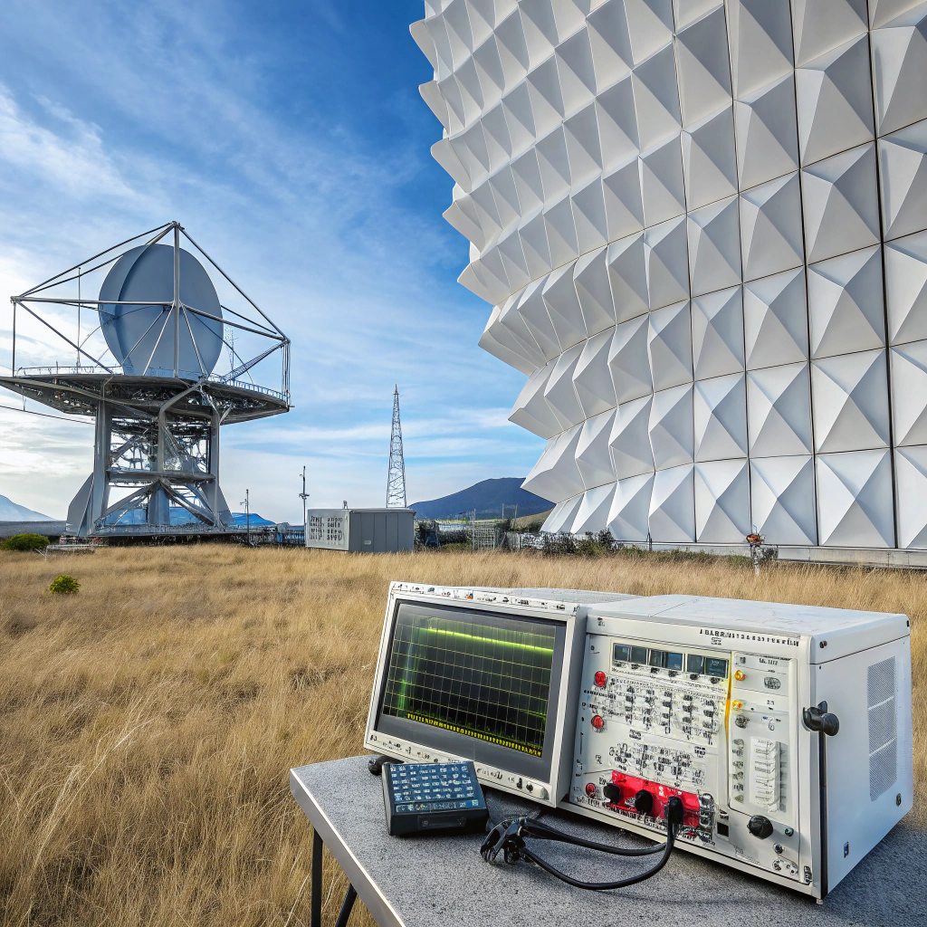
C band 2000W Power Test Result
Applications & Importance:
In radar systems, peak output power is crucial for long-range detection and resolving weak or distant targets. High peak output power allows radar systems to penetrate cluttered environments and maintain high detection accuracy.
Typical Value:
For military radar systems, peak output power typically ranges from 50 kW to 200 kW.
2. Power Gain (G)
- Definition: Power gain refers to the ratio of the output power to the input power, typically expressed in decibels (dB). It measures how much an amplifier increases the signal strength.
- Applications & Importance: High power gain is essential for enhancing the radar system's ability to detect and track targets at greater distances. A higher power gain helps to amplify weaker signals, improving radar sensitivity and accuracy.
- Typical Value: Power gain typically ranges from 40 dB to 70 dB for high-performance radar amplifiers.
3. Pulse Width (τ_pulse)
Definition:
Pulse width refers to the duration of a single pulse when the amplifier is active. This directly impacts radar resolution.
Applications & Importance:
Shorter pulse widths improve radar resolution, enabling detection of small, fast-moving, or low-RCS targets.
Typical Value:
Pulse widths for radar applications usually range from 1 µs to 1 ms, with common values between 10 µs to 100 µs.
4. Duty Cycle
Definition:
The duty cycle is the ratio of pulse width to the pulse repetition interval (PRI), determining the amplifier's effective average power output.
Applications & Importance:
Radar systems with higher duty cycles can transmit more energy in less time, allowing for faster scanning and better target tracking.
Typical Value:
For most radar systems, the duty cycle typically ranges from 0.01% to 20%.
5. Pulse Repetition Frequency (PRF)
Definition:
Pulse Repetition Frequency (PRF) refers to the number of pulses transmitted per second. It significantly influences radar range, resolution, and Doppler processing.
Applications & Importance:
PRF determines the maximum unambiguous range of radar and enhances Doppler resolution for detecting moving targets. Choosing the right PRF is critical to avoid range ambiguity and optimize radar performance.
Typical Value:
- Low PRF (for long-range detection): 100 Hz to 10 kHz
- Medium PRF (for a balance between range and Doppler resolution): 1 kHz to 10 kHz
- High PRF (for Doppler resolution and target tracking): 10 kHz to 100 kHz or higher
6. Power Efficiency (η)
Definition:
Power efficiency is the ratio of RF output power to DC input power. It determines how effectively the amplifier converts DC power into RF energy.
Applications & Importance:
Efficient amplifiers generate less heat, require less cooling, and have longer operational lifespans. In military applications, high efficiency is critical due to energy consumption and heat dissipation concerns.
Typical Value:
Solid-state RF amplifiers typically have 60% to 80% efficiency, with GaN-based amplifiers reaching up to 85% efficiency.
7. Intermodulation Distortion (IMD)
Definition:
IMD occurs when multiple input signals mix within the amplifier, generating unwanted spurious frequencies. IMD indicates the amplifier’s linearity.
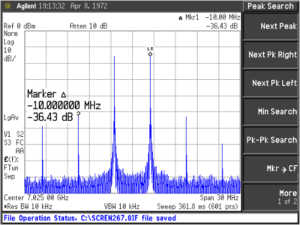
C band 2000W Power Amplifier IMD3 Test Result
Applications & Importance:
Low IMD is crucial to prevent signal interference and maintain radar accuracy, particularly in environments with multiple targets or clutter.
Typical Value:
For high-performance radar amplifiers, IMD values of -50 dBc or better are standard.
8. Third-Order Intercept Point (IP3)
Definition:
The third-order intercept point (IP3) refers to the power level where third-order intermodulation products match the fundamental signal's power level.
Applications & Importance:
A high IP3 indicates better linearity and greater capacity to handle strong signals without distortion, ensuring reliability in complex electromagnetic environments.
Typical Value:
Advanced radar amplifiers often have IP3 values of +40 dBm or higher.
9. Harmonic
Definition:
Harmonic distortion refers to the generation of harmonic frequencies in the output signal due to non-linearity in the amplifier's transfer function.
Applications & Importance:
Controlling harmonic distortion is essential to ensure radar signal fidelity and prevent interference with neighboring systems.
Typical Value:
For military radar amplifiers, harmonic distortion should be less than -50 dBc.
10. Spurious Signals
Definition: Spurious signals are unwanted frequencies generated by the amplifier that interfere with the desired signal. These can impact radar accuracy and system performance.
Applications & Importance: In military radar systems, controlling spurious signals is critical. High levels of spurious signals can cause spectral contamination, affecting target detection accuracy and overall radar system performance. A radar system requires the amplifier to maintain high linearity even under strong signal conditions to avoid significant spurious signal generation.
Typical Value: For military radar amplifiers, spurious signals are typically required to be below -60 dBc, depending on the application.
11. Input/Output VSWR (Voltage Standing Wave Ratio)
Definition:
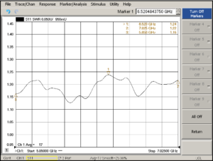
VSWR measures impedance mismatch between the amplifier and system. A high VSWR results in significant signal reflection and energy loss.
C band 2000W Power Amplifier Output VSWR Test Report
Applications & Importance:
Low VSWR ensures maximum power transfer and minimizes signal reflection, which is vital for efficient radar signal transmission.
Typical Value:
A VSWR of 1.3:1 or lower is standard for high-performance radar amplifiers.
Conclusion
RF pulsed power amplifiers are integral to the performance of radar systems. Choosing amplifiers with the right specifications is essential for ensuring high-quality, reliable radar operation. ACURAMW’s RF power amplifiers are designed to meet these demanding requirements, offering optimal performance for military, aerospace, and high-power radar applications. With over three decades of experience, we deliver amplifiers that excel in power, efficiency, linearity, and thermal management, all critical to enhancing radar capabilities in challenging environments.
More details on the RF pulsed power amplifiers which could used in the military radar in Acuramw, pls. visit our website https://acuramw.com/pulsed-power-amplifier or contact us by [email protected]

