
What Are the Main Types of Electromagnetic Material Parameter Measurement Systems?
Electromagnetic material characterization becomes challenging when materials are flexible, composite, lossy, or difficult to prepare. Choosing an unsuitable measurement method can lead to inaccurate material parameters and unreliable engineering decisions.
Electromagnetic material parameter measurement systems mainly include free-space, coaxial line, waveguide, resonant cavity, and quasi-optical cavity methods. Each technique has different measurement principles, sample requirements, frequency ranges, and accuracy levels.
Free-Space Electromagnetic Material Parameter Measurement System
I have worked with RF test antennas and electromagnetic measurement systems for more than 10 years. During my engineering career, I have helped many engineers select suitable measurement methods for different materials, including composites, absorbers, textiles, and stealth materials.
In this article, I will introduce the main electromagnetic material measurement methods and explain why free-space S-parameter measurement has become an important solution for advanced materials.
Why Do Engineers Need Different Electromagnetic Material Measurement Systems?
Different materials have different physical structures, electromagnetic properties, and measurement challenges. A method that works well for one material may not provide reliable results for another material.
Electromagnetic materials include plastics, ceramics, composites, foams, radar absorbing materials, textiles, and stealth structures. Some materials are rigid and easy to machine. Others are flexible, thin, multilayered, or difficult to cut into standard shapes.
Different measurement systems are designed for different applications.
For example:
- Fixture-based methods such as coaxial and waveguide systems require carefully prepared samples.
- Free-space systems provide a non-contact measurement approach for flexible, composite, multilayer, and difficult-to-machine materials.
- Resonant cavity systems provide very high accuracy for low-loss materials but usually operate at specific frequencies.
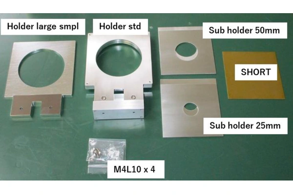
Different Sample Holders
From my experience, the first step is not choosing the instrument. The first step is understanding the material and the measurement objective.
What Factors Decide the Measurement Method?
When I help engineers select a measurement system, I usually consider several important factors:
| Factor | Why It Matters |
|---|---|
| Material structure | Determines whether fixture or non-contact measurement is suitable |
| Frequency range | Defines the suitable antenna, waveguide, or cavity design |
| Loss level | Determines whether transmission or resonance methods are preferred |
| Sample condition | Flexible or complex materials may require free-space measurement |
| Required accuracy | Higher accuracy may require specialized measurement methods |
The best measurement method is not always the one with the highest accuracy. It is the method that provides reliable data for the final engineering application.
Why Is the Free-Space Method Widely Used for Flexible and Complex Electromagnetic Materials?
Many advanced electromagnetic materials cannot be easily tested using traditional fixture-based methods. Flexible textiles, composite structures, multilayer materials, and stealth materials often have complex structures or cannot be machined into standard sample shapes.
This is where free-space measurement becomes valuable.
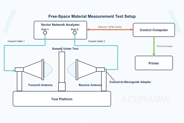
The free-space method uses horn antennas and a VNA to measure electromagnetic waves transmitted and reflected by the material. Engineers measure S11 and S21 parameters and extract important material properties, including relative permittivity, relative permeability, and loss tangent.
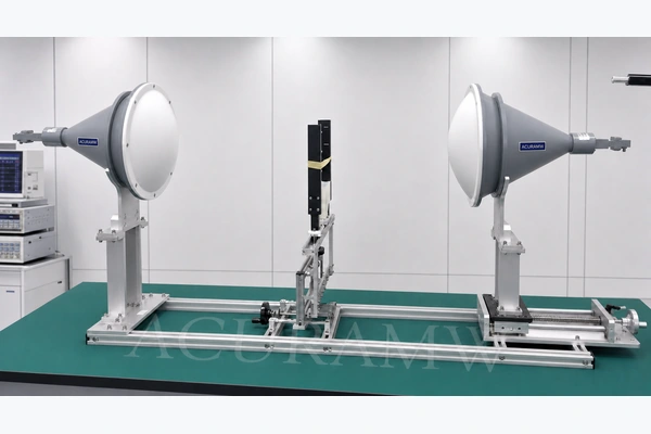
Free-space System Method_Test
Unlike fixture-based methods, free-space measurement does not require direct contact between the sample and a measurement fixture. This reduces errors caused by sample installation, air gaps, and fixture limitations.
However, free-space measurement is not simply a method for large materials. The real capability of a free-space system depends on the electromagnetic field distribution created by the antenna and lens design.
In practical applications, free-space systems mainly include two configurations:
- Collimated beam lens horn antenna systems
- Focused beam lens horn antenna systems
How Does a Collimated Beam Lens Horn Antenna System Work?
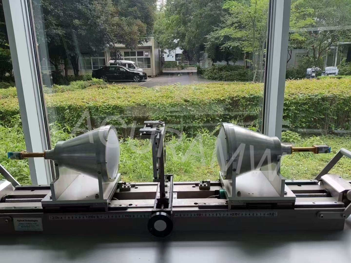
A collimated beam free-space system usually uses a horn antenna combined with a collimating lens.
The main function of the lens is to transform the divergent electromagnetic wave from the horn antenna into a more uniform and approximately plane wave.
The electromagnetic energy is distributed over a relatively large area of the material surface. The purpose is to provide stable and uniform illumination instead of concentrating energy into a small region.
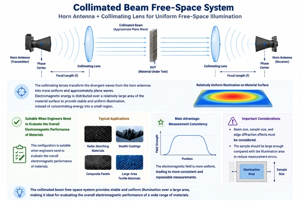
Collimated_Lens_Horn_Antenna_System
This configuration is suitable when engineers need to evaluate the overall electromagnetic performance of materials.
Typical applications include:
- Radar absorbing materials
- Stealth coatings
- Composite panels
- Large-area textile materials
The main advantage is measurement consistency because the electromagnetic field is more uniform.
However, engineers also need to consider beam size, sample size, and edge diffraction effects. The sample should be large enough compared with the illumination area to reduce measurement errors.
| Requirement | Suitable Solution |
|---|---|
| Overall electromagnetic performance evaluation | Collimated beam system |
| Uniform illumination | Collimated beam system |
| Large composite structures | Collimated beam system |
| Initial material characterization | Collimated beam system |
How Does a Spot-focusing Lens Horn Antenna System Improve Measurement Accuracy?
A focused beam free-space system uses a focusing lens to concentrate electromagnetic energy into a small focal region.
Compared with a collimated beam system, the focused beam system provides higher spatial resolution because the electromagnetic energy is concentrated in a smaller area.
This feature is valuable for advanced materials with complex structures.
For example, textile composites and stealth materials may have local variations caused by manufacturing processes. A focused beam system allows engineers to analyze specific regions instead of only obtaining average material properties.
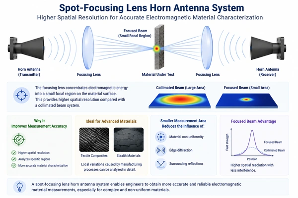
Spot-focusing-Lens-Horn-Antenna-System for Free-space method
The smaller measurement area can reduce the influence of:
- Material non-uniformity
- Edge diffraction
- Surrounding reflections
Therefore, focused beam systems are suitable for:
- Flexible materials
- Composite structures
- Multilayer materials
- Small or irregular samples
| Requirement | Suitable Solution |
|---|---|
| Local electromagnetic characterization | Focused beam system |
| Higher spatial resolution | Focused beam system |
| Flexible textile materials | Focused beam system |
| Complex composite structures | Focused beam system |
What Are the Differences Between Collimated and Focused Beam Systems?
Although both systems belong to the free-space measurement method, they create different electromagnetic field distributions.
| Feature | Collimated Beam System | Focused Beam System |
|---|---|---|
| Field distribution | Approximately uniform plane wave | Concentrated focused beam |
| Energy distribution | Larger illumination area | Smaller focal region |
| Measurement purpose | Overall material evaluation | Local material analysis |
| Spatial resolution | Lower | Higher |
| Typical applications | Panels, coatings, absorbers | Textiles, composites, multilayer materials |
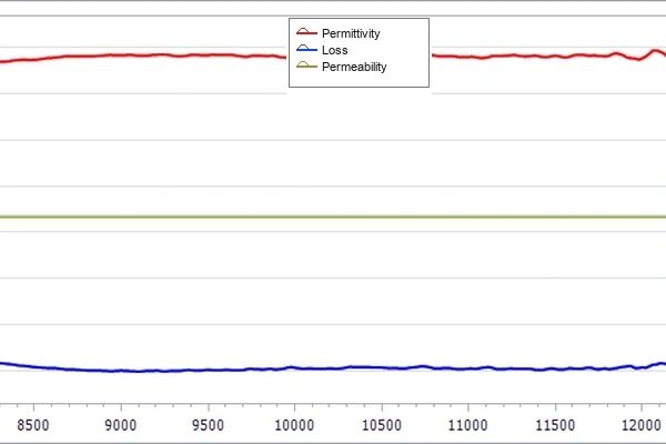
Measurement Results of PTFE with a Relative Permittivity of 2
How Can Customized Lens Horn Antennas Improve Free-Space Material Measurement?
The antenna system is one of the most important components in free-space electromagnetic material measurement.
The antenna design determines the electromagnetic field distribution, illumination area, measurement distance, and spatial resolution.
Based on my experience in RF test antenna development, I understand that different material applications require different antenna solutions.
At Acura, we provide both:
- Collimated beam lens horn antennas
- Focused beam lens horn antennas
for free-space S-parameter measurement.
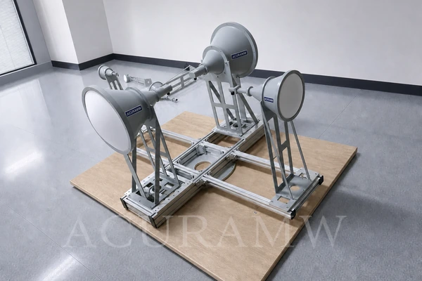
Spot-Focusing-Lens-Horn-Antenna-Series
Our lens horn antenna solutions can cover frequencies up to 300 GHz. We can also customize antenna designs according to customer requirements.
For collimated beam lens horn antennas, we can customize parameters such as gain and beam characteristics to achieve suitable illumination areas and measurement stability.
For focused beam lens horn antennas, we can customize focal distance and focal spot size according to different sample sizes, frequency ranges, and measurement requirements.
| Customized Parameter | Influence on Measurement |
|---|---|
| Frequency range | Determines applicable measurement band |
| Antenna gain | Influences measurement distance and signal level |
| Beam characteristics | Determines illumination uniformity |
| Focal spot size | Determines spatial resolution |
| Focal distance | Defines optimal sample position |
Compared with other material measurement methods, free-space measurement is unique because the antenna itself directly determines the electromagnetic field distribution.
A properly designed lens horn antenna helps engineers achieve reliable S-parameter measurements and accurate extraction of dielectric constant, permeability, and loss tangent.
How Does a Coaxial Air Line Method Measure Electromagnetic Material Parameters?
The coaxial air line method is one of the widely used transmission/reflection methods for electromagnetic material characterization.
This method uses a coaxial fixture to measure the S-parameters of a ring-shaped material sample. By measuring S11 and S21 with a VNA, engineers can extract complex permittivity and permeability of solid materials.
The coaxial air line method is mainly used for high-loss materials where accurate broadband characterization is required.
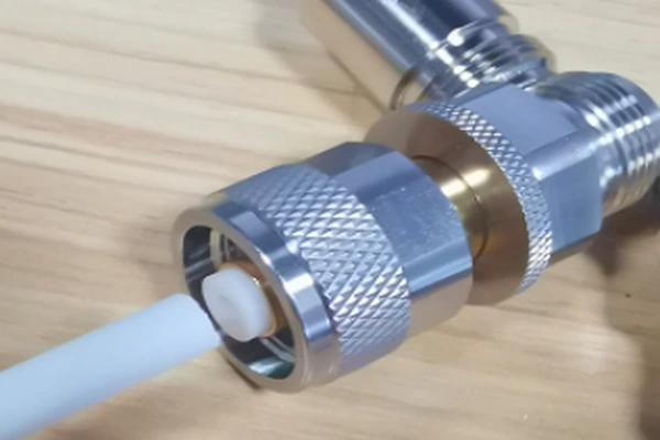
Test_Material_For_Coaxial_Airline_Method
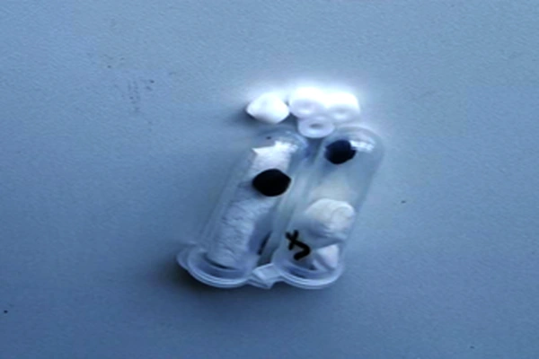
Coaxial Air Line Method Sample Holder for Electromagnetic Material Parameter Measurement
According to SJ20512 and equivalent international measurement methods such as ASTM D5568, the coaxial air line system uses transmission/reflection principle to measure complex dielectric constant and magnetic permeability.
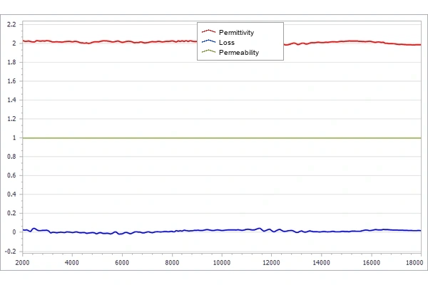
Measured Electromagnetic Parameters of PTFE Using Coaxial_Airline_Method
Typical frequency coverage can reach approximately 0.3–40 GHz with different frequency bands.
The sample requirement is one of the most important factors.
The material sample usually needs to be machined into a ring shape with accurate dimensions to fit the coaxial fixture.
Typical requirements include:
- No air gaps
- No cracks
- Uniform material structure
- Accurate machining dimensions
| Feature | Description |
|---|---|
| Measurement principle | Transmission/reflection method |
| Sample shape | Ring-shaped sample |
| Measured parameters | Complex permittivity and permeability |
| Typical frequency range | 0.3–40 GHz |
| Suitable materials | High-loss solid materials |
| Standard | SJ20512 |
The main advantages of the coaxial air line method include:
- Wide frequency coverage
- Stable measurement environment
- Automated measurement process
- Suitable for dielectric and magnetic material characterization
However, the sample preparation requirement is also a limitation. Machining errors, air gaps, and sample deformation may influence the extracted material parameters.
How Does a Waveguide Air Line Method Measure Electromagnetic Material Parameters?
The waveguide air line method is another important transmission/reflection technique for electromagnetic material characterization.
Unlike the coaxial air line method, the waveguide method uses rectangular waveguide fixtures and requires rectangular material samples.
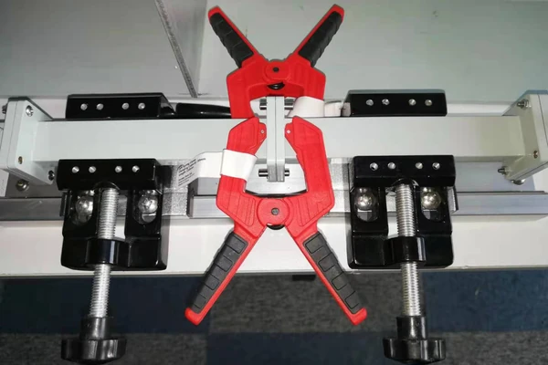
Waveguide Air Line Method Test Fixture
The waveguide structure controls the electromagnetic field propagation inside the measurement fixture. This allows engineers to achieve accurate material parameter extraction within specific frequency bands.
According to the SJ20512 standard, the waveguide air line method also uses the transmission/reflection principle to measure complex permittivity and permeability of solid materials.
Compared with coaxial air line systems, waveguide systems usually provide higher accuracy within their designed frequency bands.
Typical frequency coverage can reach approximately 1.7–40 GHz with multiple waveguide bands.
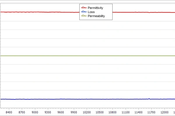
Measured Electromagnetic Parameters of PTFE Using Waveguide Air Line Method
TThe sample requirement is usually a rectangular shape.
For example, in common waveguide bands, the sample dimensions must match the waveguide cross-section to ensure accurate electromagnetic propagation.
| Feature | Description |
|---|---|
| Measurement principle | Transmission/reflection method |
| Sample shape | Rectangular sample |
| Measured parameters | Complex permittivity and permeability |
| Typical frequency range | 1.7–40 GHz |
| Suitable materials | Solid dielectric and magnetic materials |
| Standard | SJ20512 |
The main advantages of the waveguide air line method include:
- Higher accuracy within specific frequency bands
- Easier sample preparation compared with coaxial ring samples
- Stable electromagnetic field control
- Automated measurement capability
The limitation is that each waveguide size only works within a specific frequency range. Engineers need to select the correct waveguide band according to the test frequency.
When Should Engineers Choose Resonant Cavity Measurement Systems?
When engineers need very high accuracy for low-loss materials, resonant cavity systems are often a suitable choice.
Unlike transmission/reflection methods, resonant cavity methods characterize materials by analyzing changes in resonant frequency and quality factor (Q-factor).
When a material sample is placed inside the resonant cavity, it changes the electromagnetic field distribution inside the cavity. These changes can be used to extract dielectric and magnetic properties with very high accuracy.
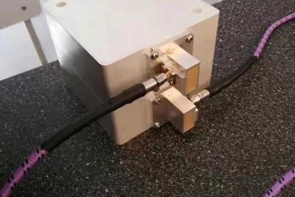
Resonant Cavity Method Electromagnetic Material Measurement System
Resonant cavity systems are commonly used for:
- Ceramic materials
- Low-loss plastics
- Microwave dielectric materials
- High-performance RF materials
Compared with broadband transmission methods, resonant cavity systems usually operate at a single frequency or several designed frequencies.
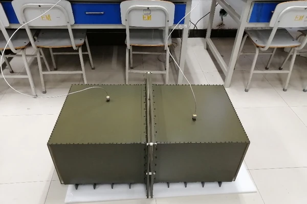
300–1000 MHz Multimode Resonant Cavity Method Test System
| Feature | Description |
|---|---|
| Measurement principle | Resonant frequency and Q-factor variation |
| Accuracy | Very high for low-loss materials |
| Frequency | Single frequency or several customized frequencies |
| Sample type | Flat and thin material samples |
| Typical application | Precision electromagnetic material characterization |
The main advantages of resonant cavity measurement systems include:
- Extremely high measurement accuracy for low-loss materials
- Simple sample preparation
- High measurement repeatability
- Automated measurement operation
However, the limitation is that resonant cavity systems usually cannot provide broadband material characterization. Engineers need to select the appropriate cavity frequency according to the material application.
How Does a Quasi-Optical Cavity Method Measure High-Frequency Materials?
When engineers need to characterize low-loss materials at millimeter-wave frequencies, quasi-optical cavity systems provide an effective solution.
A quasi-optical cavity method uses electromagnetic wave propagation principles similar to optical systems. It is designed for high-frequency measurement where traditional coaxial or waveguide structures become difficult to implement.
This method is especially suitable for materials used in:
- Millimeter-wave communication systems
- High-frequency RF components
- Advanced dielectric materials
- Low-loss microwave substrates
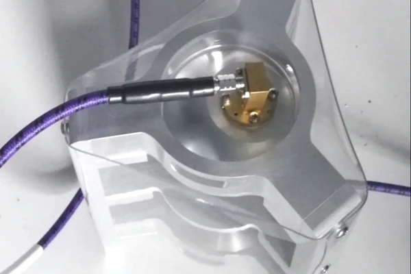
40-70GHz Quasi-Optical Cavity Electromagnetic Material Measurement System
The quasi-optical cavity method provides accurate measurement of dielectric properties at high frequencies by using resonant behavior in a controlled electromagnetic environment.
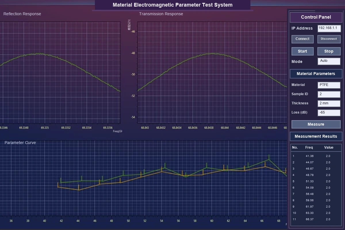
Quasi_Optical_Cavity_Method_Measurement_Software
Compared with conventional resonant cavity systems, quasi-optical cavity systems extend measurement capability into higher frequency ranges.
| Feature | Description |
|---|---|
| Measurement principle | High-frequency resonant electromagnetic field analysis |
| Frequency range | Millimeter-wave frequency range |
| Typical frequency | 40–70 GHz |
| Suitable materials | Low-loss dielectric materials |
| Main advantage | High accuracy at high frequencies |
The main advantages of quasi-optical cavity systems include:
- Suitable for millimeter-wave materials
- High measurement accuracy
- Good repeatability
- Simple sample preparation
For engineers developing next-generation RF and microwave materials, quasi-optical cavity measurement provides important characterization capability beyond traditional frequency ranges.
How Can Engineers Select the Right Material Characterization Method?
Selecting the correct electromagnetic material measurement method requires a balance between material properties, frequency range, sample condition, and accuracy requirements.
Different methods have different advantages. Engineers should select the method according to the actual application instead of choosing a system only based on measurement accuracy.
| Material Type | Recommended Method |
|---|---|
| Flexible and complex materials | Free-space system |
| Large-area materials and absorbers | Collimated beam free-space system |
| Local material variation analysis | Focused beam free-space system |
| Ring-shaped samples | Coaxial air line system |
| Rectangular samples | Waveguide air line system |
| Low-loss precision materials | Resonant cavity system |
| Millimeter-wave low-loss materials | Quasi-optical cavity system |
The following factors should also be considered:
| Selection Factor | Engineering Consideration |
|---|---|
| Material structure | Determines sample preparation and suitable measurement method |
| Frequency range | Determines antenna, waveguide, or cavity design |
| Loss characteristics | Determines whether transmission or resonance methods are preferred |
| Measurement accuracy | Determines whether a standard or high-precision method is required |
| Application requirements | Determines the most practical measurement solution |
From my experience, the most important question is not which method has the highest accuracy.
The important question is which method provides reliable information for the final engineering decision.
For example, a defense engineer developing stealth textiles may need a focused beam free-space system to analyze local material variations.
A researcher developing low-loss ceramic materials may need a resonant cavity system for high-precision characterization.
A material manufacturer producing broadband absorbing materials may prefer a free-space or waveguide transmission method.
The best measurement solution always depends on the material, frequency range, and engineering objective.
Conclusion
Different electromagnetic material measurement systems serve different materials and applications.
Free-space, coaxial air line, waveguide air line, resonant cavity, and quasi-optical cavity methods each provide unique advantages.
Selecting the right measurement method helps engineers achieve accurate material characterization and make better product development decisions.